and some sophistication. The chapter concludes by introducing the regenerator showing how it improves efficiency.
 Essentially, these chapters showed that at the Stirling
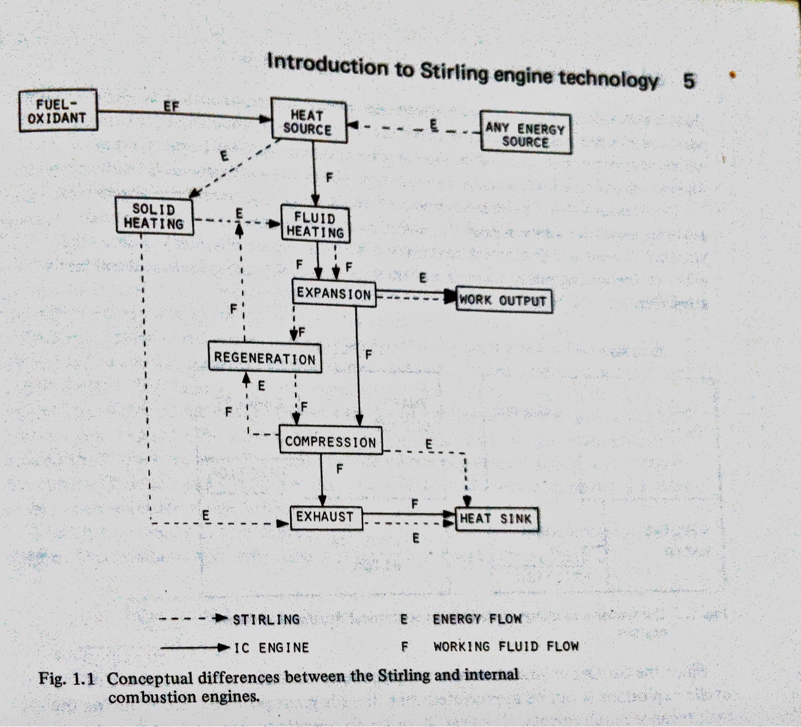
Engine despite being a very complex machine can be explained using everyday
observations, but full understanding of the Engine requires more knowledge. At
its very basics the Stirling Engine is an air-tight box, in which a pressurized
gas is heated and cooled by an external heat source which increases and
decreases the pressure within the box, moving a piston up and down. Since more
work has to be applied to move the piston upwards than downwards, mechanical energy
can be created. Interestingly, when heat is put into a Stirling Engine
mechanical energy is outputted, but if mechanical energy is put into a Stirling
Engine (by rotating its flywheel) hot and cold heat is outputted (Chapter 1.2).
Although I understand how the former works, this system confuses me as
depending on the direction the flywheel is rotated the location of the hot and
cold heat also reverses. After reading chapters 2.1 (Thermodynamics) and 2.2
(Heat Transfer) I will hopefully better understand how this works.
Essentially, these chapters showed that at the Stirling
Engine despite being a very complex machine can be explained using everyday
observations, but full understanding of the Engine requires more knowledge. At
its very basics the Stirling Engine is an air-tight box, in which a pressurized
gas is heated and cooled by an external heat source which increases and
decreases the pressure within the box, moving a piston up and down. Since more
work has to be applied to move the piston upwards than downwards, mechanical energy
can be created. Interestingly, when heat is put into a Stirling Engine
mechanical energy is outputted, but if mechanical energy is put into a Stirling
Engine (by rotating its flywheel) hot and cold heat is outputted (Chapter 1.2).
Although I understand how the former works, this system confuses me as
depending on the direction the flywheel is rotated the location of the hot and
cold heat also reverses. After reading chapters 2.1 (Thermodynamics) and 2.2
(Heat Transfer) I will hopefully better understand how this works.
The chapter ends introducing the Regenerator which I found
to be a neat, yet very simple idea. Basically, instead of having the heat
sources cool the hot gas all the way down to a cold temperature and losing all
the energy they had the gas flows through a regenerator collecting some of the
heat. Without getting too complex, a regenerator is a group of stainless steel
wires that the gas flows through to pre-cool or pre-heat the gas. This is
because when the gas flows from hot to cold the gas is hotter than the
regenerator. Therefore, the gas gives some of its heat to the regenerator,
cooling the gas while heating the regenerator. When the gas returns, moving
from cold to hot, the gas is colder than the regenerator and therefore is
preheated returning some of the energy it lost during the previous phase. As a
result the regenerator pre-heats and pre-cools the gas, using energy that would
otherwise be lost which makes the engine more efficient. The other parts of the
Stirling Engine are discussed in chapter 1.4, which will be posted shortly.
No comments:
Post a Comment